Compare inline, parallel-shaft, helical-bevel, and heli…
A gear reducer changes the relationship between input speed and output torque to suit the driven equipment. Selecting a suitable unit requires both a mechanical layout that fits the machine and ratings that match the operating load.
R, F, K, and S are widely used series designations for several common gearbox arrangements. The descriptions below explain these typical configurations. Exact construction, dimensions, and ratings must always be checked against the supplier’s documentation.
R, F, K, and S are widely used series designations for several common gearbox arrangements. The descriptions below explain these typical configurations. Exact construction, dimensions, and ratings must always be checked against the supplier’s documentation.
The Main Differences at a Glance
| Series | Typical Gear Arrangement | Drive Layout | Main Layout Consideration |
|---|---|---|---|
| R | Inline helical | Input and output arranged in line | An aligned drive installation |
| F | Parallel-shaft helical | Parallel, offset axes | Offset positioning within available space |
| K | Helical-bevel | Right-angle arrangement | Changing drive direction by 90 degrees |
| S | Helical-worm | Right-angle arrangement | A worm-based reduction arrangement |
R Series: Inline Helical Gear Reducers
R series gear reducers use an inline layout. This arrangement can suit machinery where the motor and driven connection are positioned along an aligned drive axis.
When reviewing an R series configuration, confirm the required ratio, output torque, output shaft dimensions, and mounting interface. Check the complete assembly dimensions, including the motor or input adapter.
When reviewing an R series configuration, confirm the required ratio, output torque, output shaft dimensions, and mounting interface. Check the complete assembly dimensions, including the motor or input adapter.
F Series: Parallel-Shaft Helical Gear Reducers
F series gear reducers use parallel input and output axes with an offset between them. This layout can be useful when the drive must sit alongside the driven shaft or fit a particular machine envelope.
Selection should include output connection details and available installation space. Where a hollow-shaft version is proposed, the machine shaft dimensions and the method of securing the gearbox must also be confirmed.
Selection should include output connection details and available installation space. Where a hollow-shaft version is proposed, the machine shaft dimensions and the method of securing the gearbox must also be confirmed.
K Series: Helical-Bevel Gear Reducers
K series gear reducers use a right-angle arrangement with helical-bevel gearing. This changes the direction of power transmission and can help position the motor around the machine layout.
The right-angle form does not, by itself, establish load capacity. Operating torque, peak loads, shaft forces, and duty conditions must be checked for the selected model.
The right-angle form does not, by itself, establish load capacity. Operating torque, peak loads, shaft forces, and duty conditions must be checked for the selected model.
S Series: Helical-Worm Gear Reducers
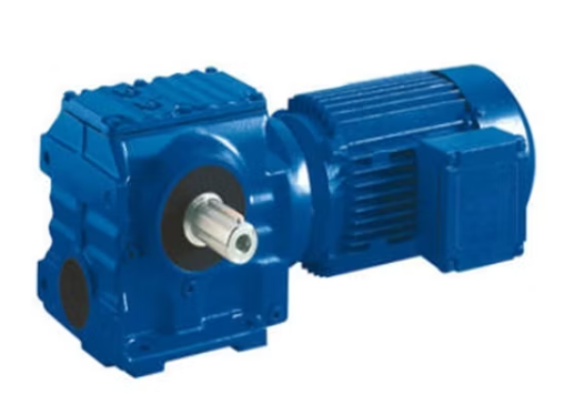
S series gear reducers typically combine helical and worm gearing in a right-angle layout.
Selection should consider both mechanical loading and thermal operating conditions. Ratio, input speed, running time, lubrication, and ambient temperature can affect suitability.
Do not assume that an S series gearbox is self-locking or suitable for holding a suspended load. Any holding or braking function requires a separate assessment.
Selection should consider both mechanical loading and thermal operating conditions. Ratio, input speed, running time, lubrication, and ambient temperature can affect suitability.
Do not assume that an S series gearbox is self-locking or suitable for holding a suspended load. Any holding or braking function requires a separate assessment.
Can One Brand Replace Another?
Matching series letters or nominal ratios does not confirm interchangeability. Shaft sizes, mounting dimensions, torque ratings, input adapters, and lubrication arrangements may differ.
For a replacement enquiry, provide the full existing model code, nameplate, installation drawing, and photographs of the connections.
For a replacement enquiry, provide the full existing model code, nameplate, installation drawing, and photographs of the connections.
Find the Right Gear Reducer for Your Equipment
Contact EHAI with your required output speed, torque, motor details, and installation layout. Include operating conditions so the proposed configuration can be reviewed against the application.