
F Series Helical Gear Reducer
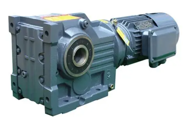

Typical applications include conveyors, material-handling equipment and processing machinery. Depending on the selected model, the reducer may be supplied with a solid or hollow output shaft and different mounting arrangements.
Select the unit according to the required output speed, torque, service factor and operating cycle. Verify shaft dimensions, mounting interfaces, permissible shaft loads and lubrication requirements before installation.
| Parameter | Specification |
|---|---|
| Drive Configuration | Parallel-shaft helical gear reducer with integrated motor, motor adapter or shaft input |
| Motor Type | Three-Phase AC Induction Motor; servo motor configurations available with suitable adapters |
| Rated Motor Power | 0.12–200 kW, depending on gear unit size, ratio and motor connection |
| Rated Voltage | Motor options include 220–240 V, 380–400 V, 415–440 V and 660–690 V |
| Rated Frequency | 50 Hz or 60 Hz, according to the selected motor rating |
| Motor Rated Speed | Selected according to motor pole count, supply frequency and required output speed |
| Rated Current | Specified for the selected motor power, voltage and frequency |
| Motor Efficiency Class | IE3 motor packages available; other classes subject to motor selection |
| Motor Protection Rating | IP55 motor packages available; special protection configurations subject to confirmation |
| Insulation Class | Class F motor packages available |
| Operating Duty | S1 continuous-duty motor packages available; intermittent duty requires separate selection |
| Brake Option | Optional brake motor; brake torque selected for the application |
| Inverter Operation | Suitable motor configuration required; verify cooling, torque and gearbox speed limits |
| Parameter | Specification |
|---|---|
| Gear Type | Parallel-Shaft Helical Gear Reducer |
| Gear Unit Size | Sizes include F27, F37, F47, F57, F67, F77, F87, F97, F107, F127 and F157; numbering varies by product configuration |
| Output Shaft | Solid shaft, keyed hollow shaft, shrink-disc hollow shaft or splined hollow shaft |
| Mounting Arrangement | Foot-mounted, flange-mounted or shaft-mounted; B5/B14 flange options on selected configurations |
| Shaft / Bore Diameter | Solid shaft diameters: 25–120 mm; hollow bore dimensions depend on connection type |
| Input Connection | Integrated gearmotor, IEC motor adapter, servo adapter or solid input shaft |
| Net Weight | Specified for the selected size, mounting arrangement and motor package |
| Overall Dimensions | Solid output shaft extensions: 50–210 mm; housing dimensions depend on configuration |
| Mechanical Specifications | Specification |
|---|---|
| Reduction Ratio | Standard two-/three-stage units: 3.77–281.71; combined reduction units: 87–31,434 |
| Rated Output Torque | Model-dependent maximum output torque ratings: 130–20,000 Nm |
| Output Speed | At 1,450 rpm input: approximately 5.15–384.62 rpm for standard units; 0.046–16.67 rpm for combined units |
| Permissible Input Speed | Selected according to ratio, bearing speed, thermal capacity and lubrication conditions |
| Service Factor | Selected according to driven load, daily operating hours, starting frequency and shock loading |
| Gear Stages | Two or three stages for standard units; additional stages for combined reduction configurations |
| Permissible Shaft Loads | Radial and axial limits specified for the selected size, speed and load application point |
| Lubrication | Gear oil lubrication; oil grade and quantity matched to mounting position and operating conditions |
| Operating Temperature | Permitted range determined by lubricant, seals, motor and thermal loading |
| Optional Features | Brake motor, reduced backlash, torque arm, backstop or special shaft connection, depending on configuration |
Provide the required output speed, torque, motor power, operating hours, starting frequency and mounting position. Include any shock loads and radial or axial forces acting on the output shaft.
The F series described here uses a parallel-shaft arrangement. Check the dimensional drawing to confirm the shaft positions and installation layout.
Divide the input speed by the required output speed to estimate the ratio. Select an available ratio and verify output torque, service factor and gearbox capacity.
Motorized units and motor-adapter configurations may be available. Confirm the motor rating, electrical supply, mounting interface and any brake requirements when ordering.
Availability depends on the model. Confirm the shaft or bore diameter, connection method and mounting requirements using the selected unit’s drawing.